Hardware List
Tools Needed
- 2.5mm allen key
- 4mm allen key
- Pliers for turning in the drill guides
- 6 x M4x12 allen cap screws
- 2 x M4 knobs
- Vernier caliper (optional)
Dimensional Accuracy
If you’re concerned about dimensional accuracy, I’d suggest the following to ensure good results.
Printing the Dowel Jig Head, stop the print after maybe 5 or so layers, and let the print completely cool before removing it from the bed.
If your print has an elephants foot, either debur it carefully, or avoid it when measuring. Measure the complete length of the head. PLA will shrink slightly, so it’ll likely be a bit under 150mm which is the length the model is designed to be.
If for example, your test print comes out to 149mm, then you’ll want to scale the actual print up to compensate for this shrinkage.
To calculate this, you’ll need to calculate the percentage difference between your test print and the desired dimension.
As an example, your the test print comes out at 148.3mm, and we want it to be 150mm.
First, find the difference between the two numbers. 150-148.3=1.7
Take the result, and divide it by the initial value, so 1.7 / 148.3 = 0.01146
Then finally, multiply this by 100.
0.01146 * 100 = 1.14632
Scale your part in the X and Y direction by this number, so 101.14632%
Of course your part will shrink again slightly, but this should get you very close. I managed to get my jig to measure 149.98mm after printing, which I’m happy with.
Printing Guidelines
I printed this entirely in grey PLA, firstly because PLA is easy to print, very stiff and has minimal shrinkage. I don’t think PETG or anything fancy is needed for this to work well.
All parts are printed at quite high infill percentages.
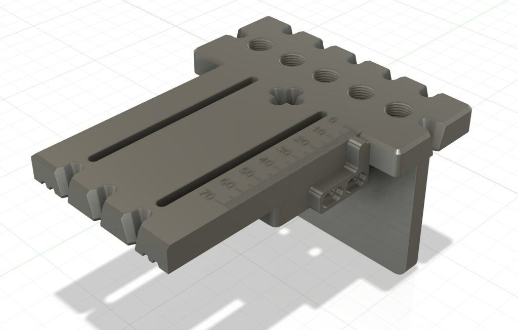
Dowel Jig Head
Infill: 80%
Colour: Grey (better visibility of markings)
Print using variable layer height, all layers at 0.2mm, the top 3 or 4 layers are better if printed at 0.08mm or similar. This makes the measuring lines and text far more visible.
Fence Vertical
Infill: 100%
This part will have clamping force applied, so it needs to be strong.
Fence Interface
Infill: 80%*
Fence Support
Infill: 80%*
Fence Indicator
Infill: 100%
This again will have some force applied to it through the screws holding it in place.
*One of the reasons I suggest 80% for these parts is it makes the threaded inserts go in a bit easier. I found on parts that were 100%, the inserts had quite a bit of difficulty threading into the part.
Assembly Instructions
Thread the 8 M4 inserts into the holes in the print, make sure they seat fully in their holes.
Thread the drill guides in place. These will be very tight.
Assemble the fence by attaching the vertical fence to the interface with the fence support.
Attach the head to the fence with the 2 knobs.
And finally, install the indicator on the side. The indicator should measure to the center of the holes. I’m sure you can work out how to set it.
I don’t have much more to say really, I may make a short video of the assembly process. Feel free to leave a comment if you have any feedback or questions.
2 responses to “3D Printed Dowel Jig”
-
Do you have an imperial version?
-
Yes, just published it today, here is the link: https://makerworld.com/en/models/1692690-adjustable-dowelling-jig-imperial-metric#profileId-1794383
-


Leave a Reply