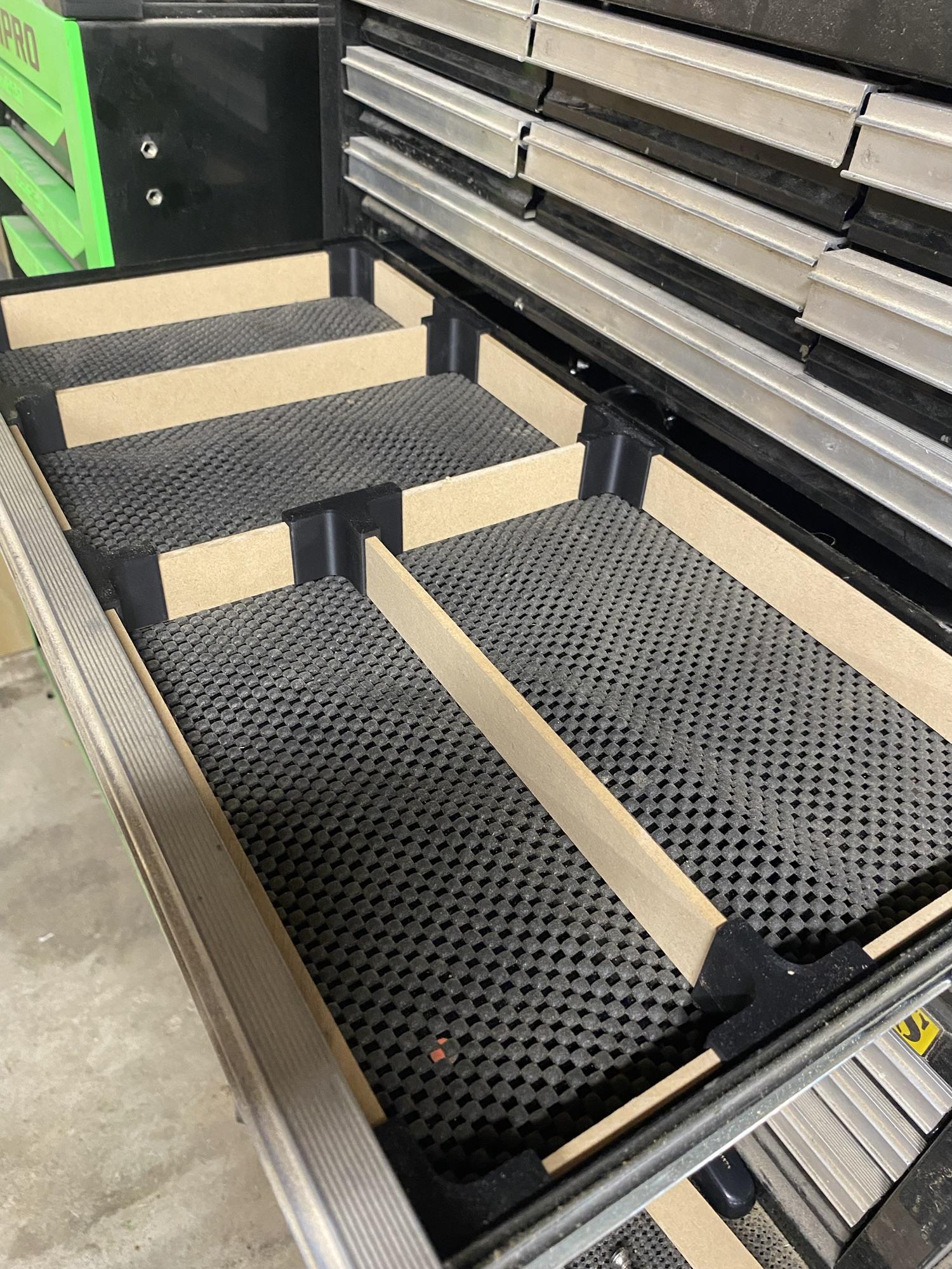
I wanted to cut a grid of slots into my new workbench that would fit dovetail clamps (or Matchfit if you’re buying the branded ones).
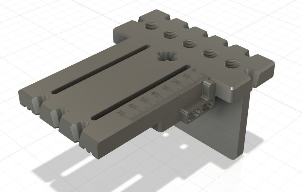
So I designed a 3d printable jig that has adjustable spacing, and can easily be modified to suit other router types.
Download it here is you want it:
https://makerworld.com/en/models/1222054-router-jig-for-microjig-matchfit-dovetail-slots
The only thing I may change is to add some kind of dust collection, perhaps some kind of channel behind the router bit with an attachment for a vacuum hose.
Assembly Instructions
Hardware list:
- 2x M6 bolts, 50mm+ long
- 2X M6 washers
- 2X M6 wingnuts or standard nuts
- 2x 20mm – 50mm wood screws (for attaching the handle)
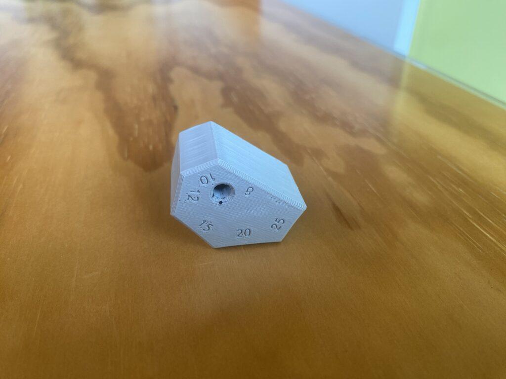
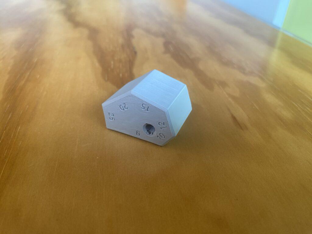
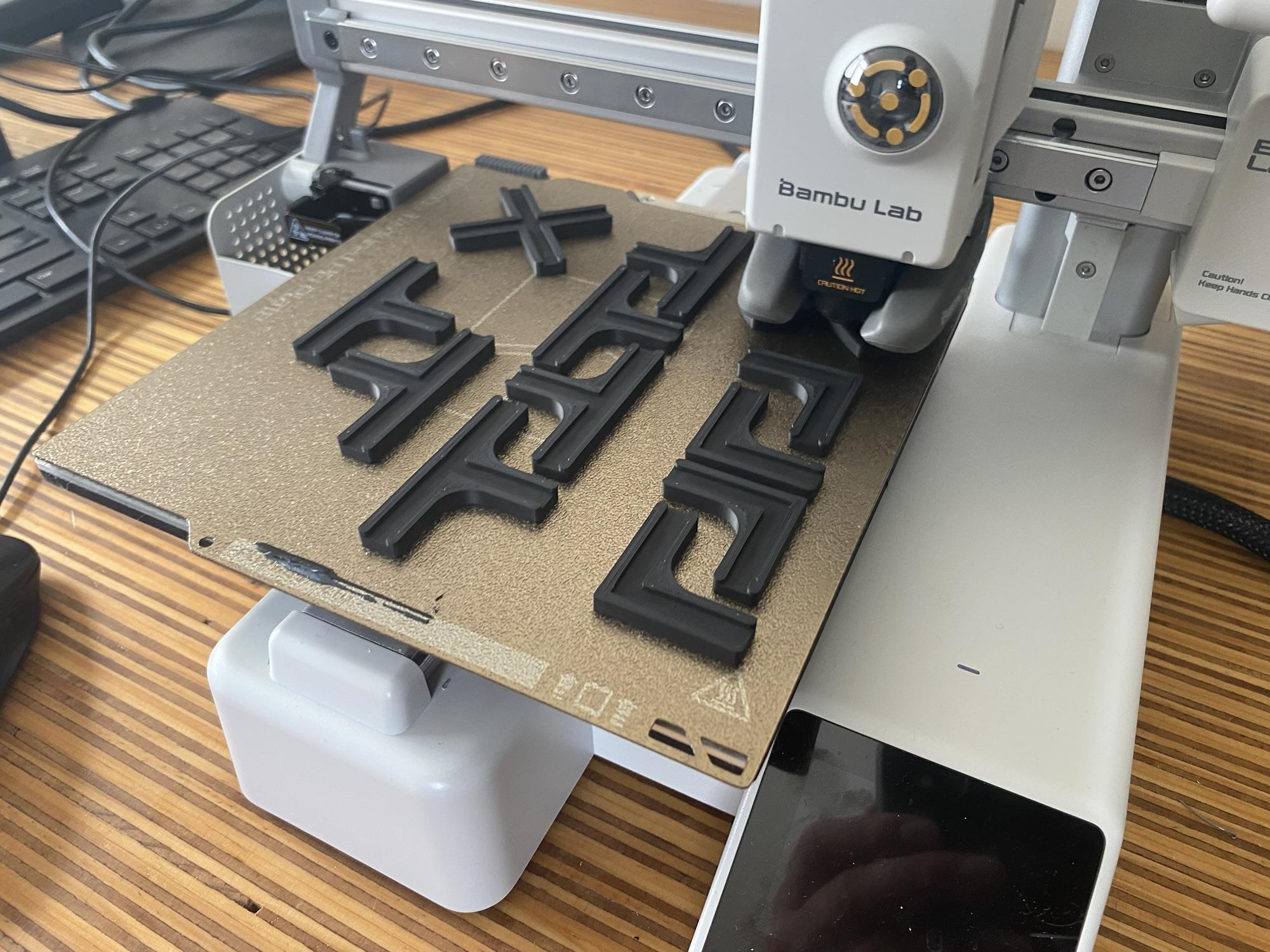
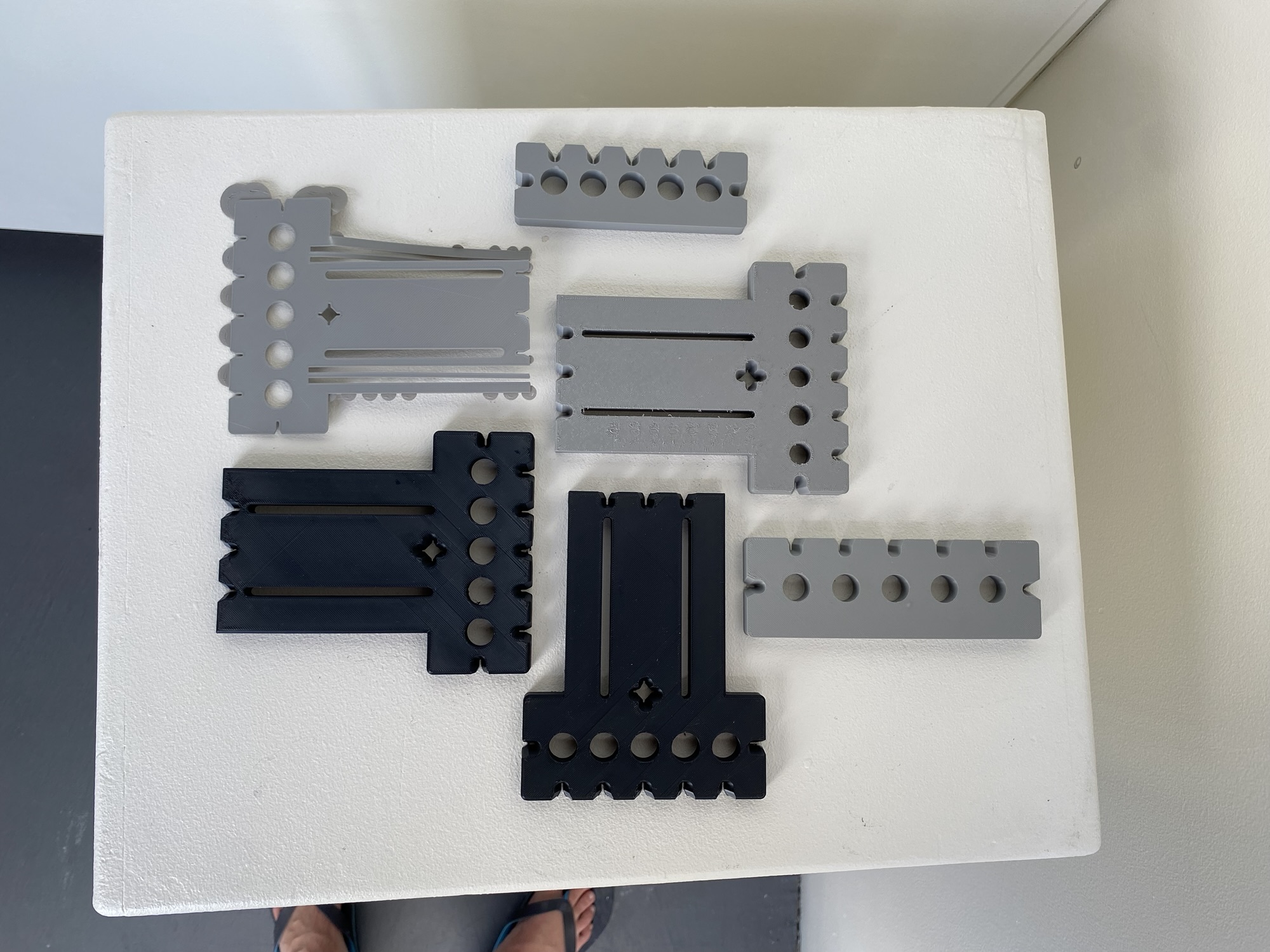
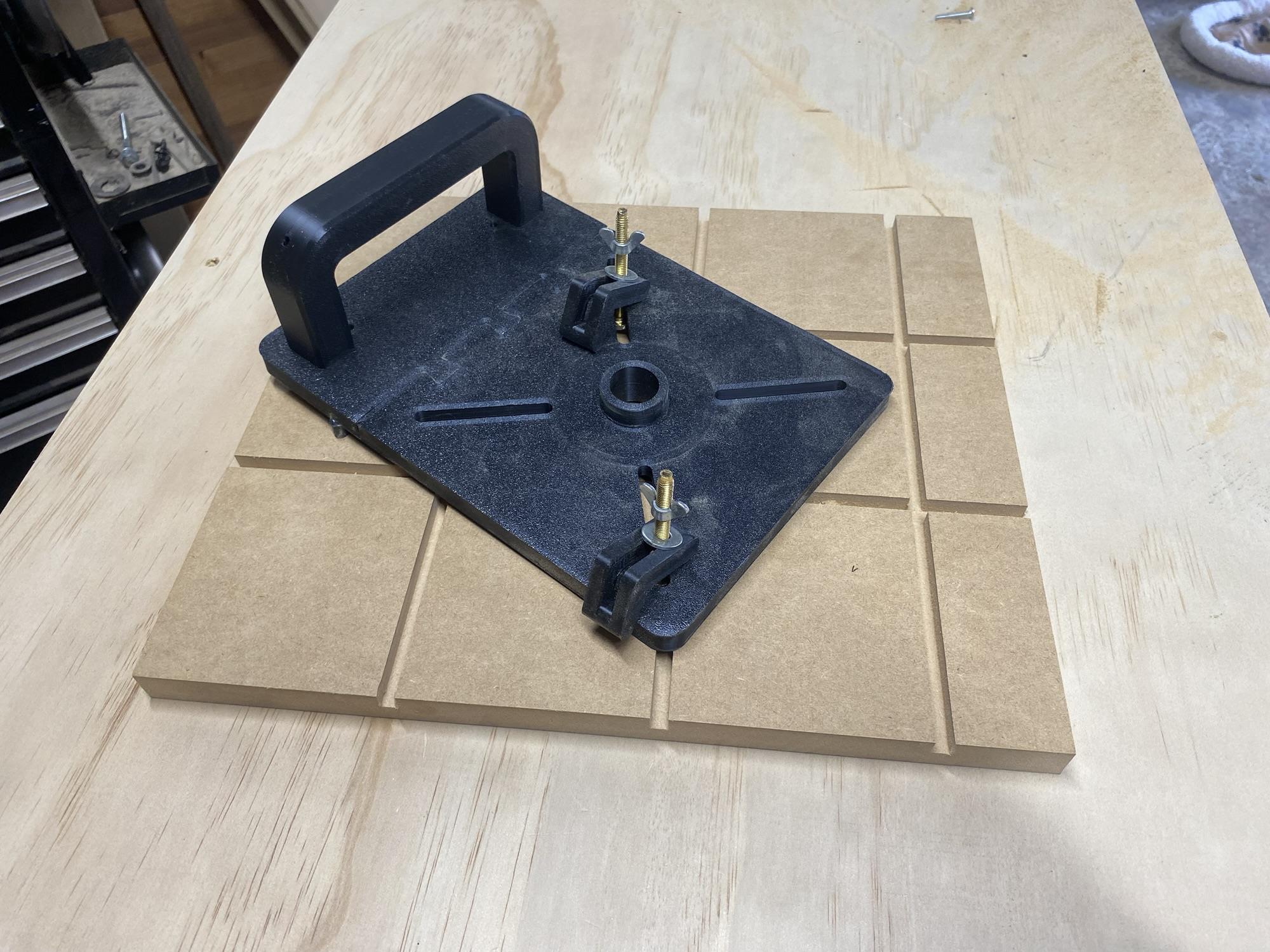
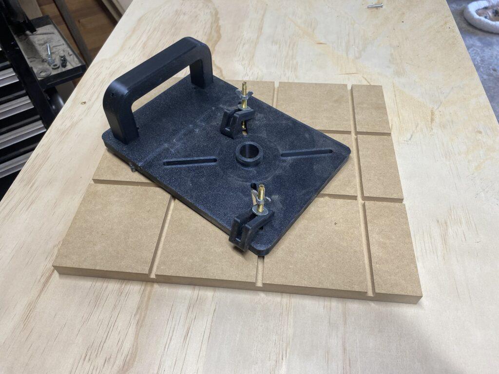
Print out the main base, and print out which sub base suits the spacing you want, the sub base you use dictates what spacing you get. Print all remaining parts.
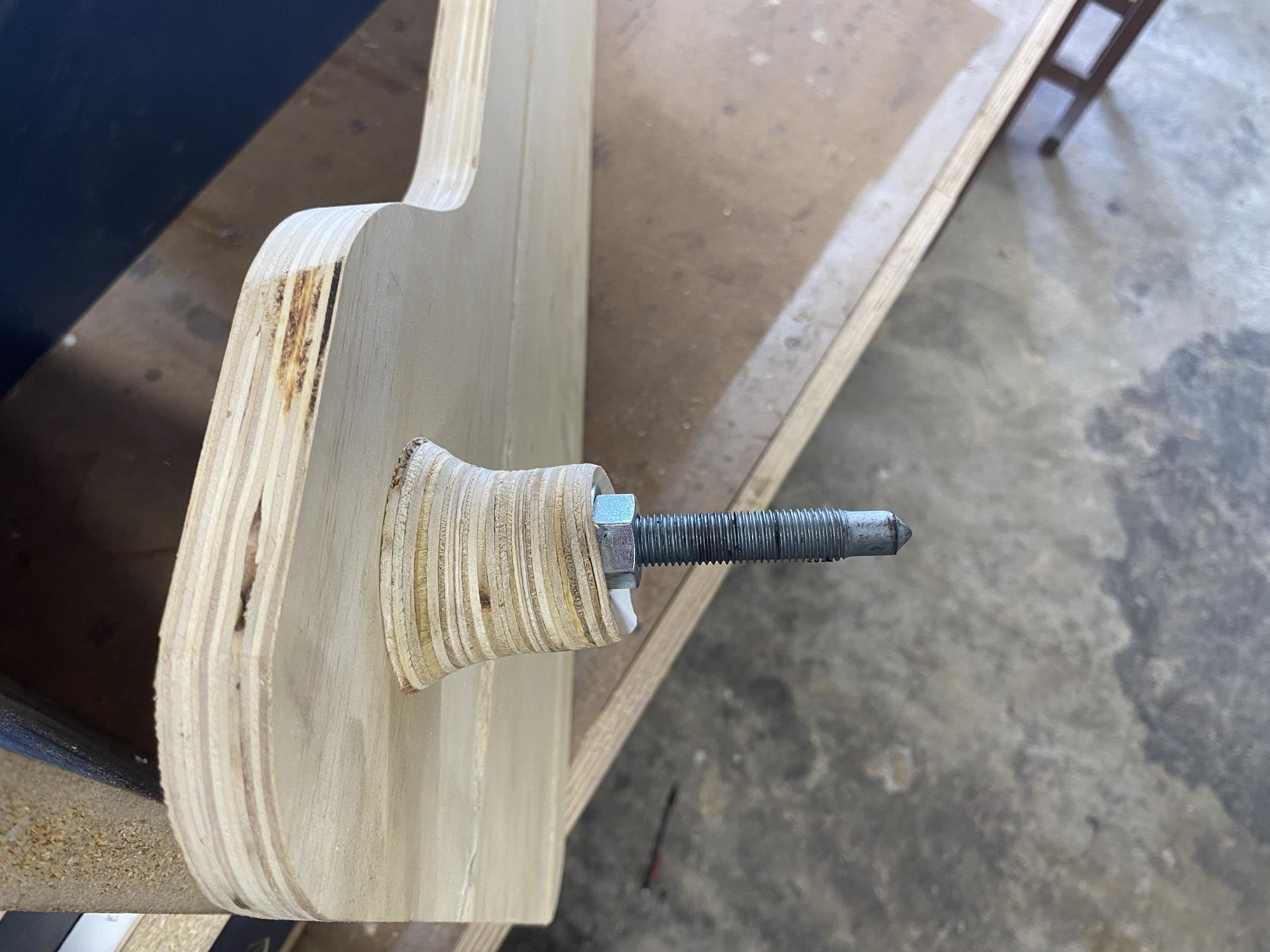
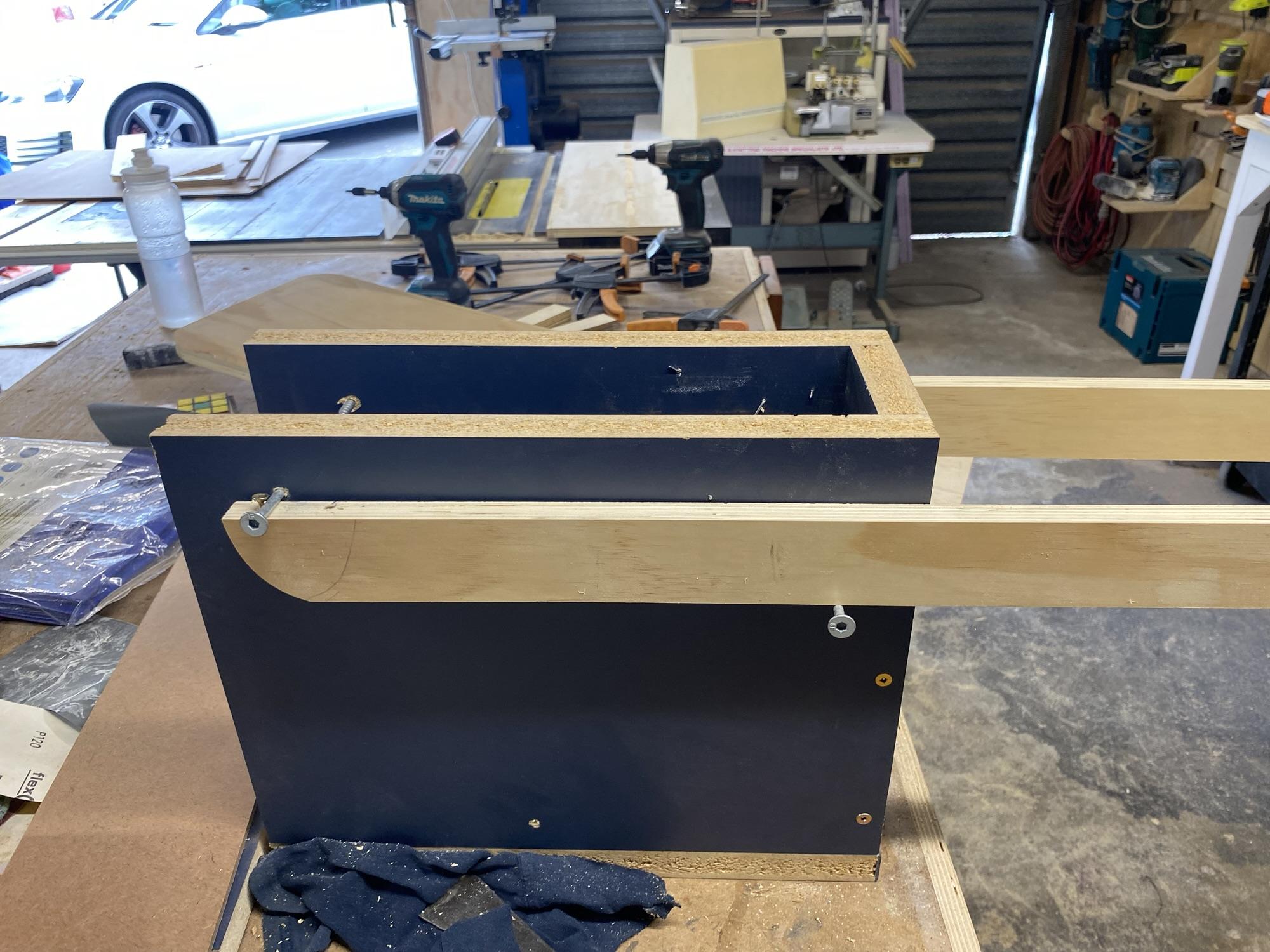
Attach the sub base to the main base, use some CA glue. Glue the guide rail in place. Screw in the guide bushing. This is very tight, so perhaps use some water pump pliers, but be careful.
If you want a handle, print that as well, otherwise you can use any handle which has either 96mm or 128mm spacing (both are common spacings).
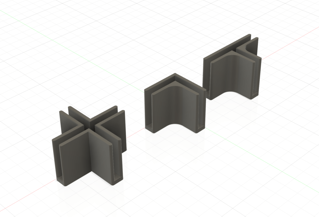
Finally, print 2 of the clamps, larger ones for larger routers, the small ones work well for little trim routers.
You’ll also need some bolts and nuts to attach the clamps. I used some M6 bolts and a couple wing nuts.
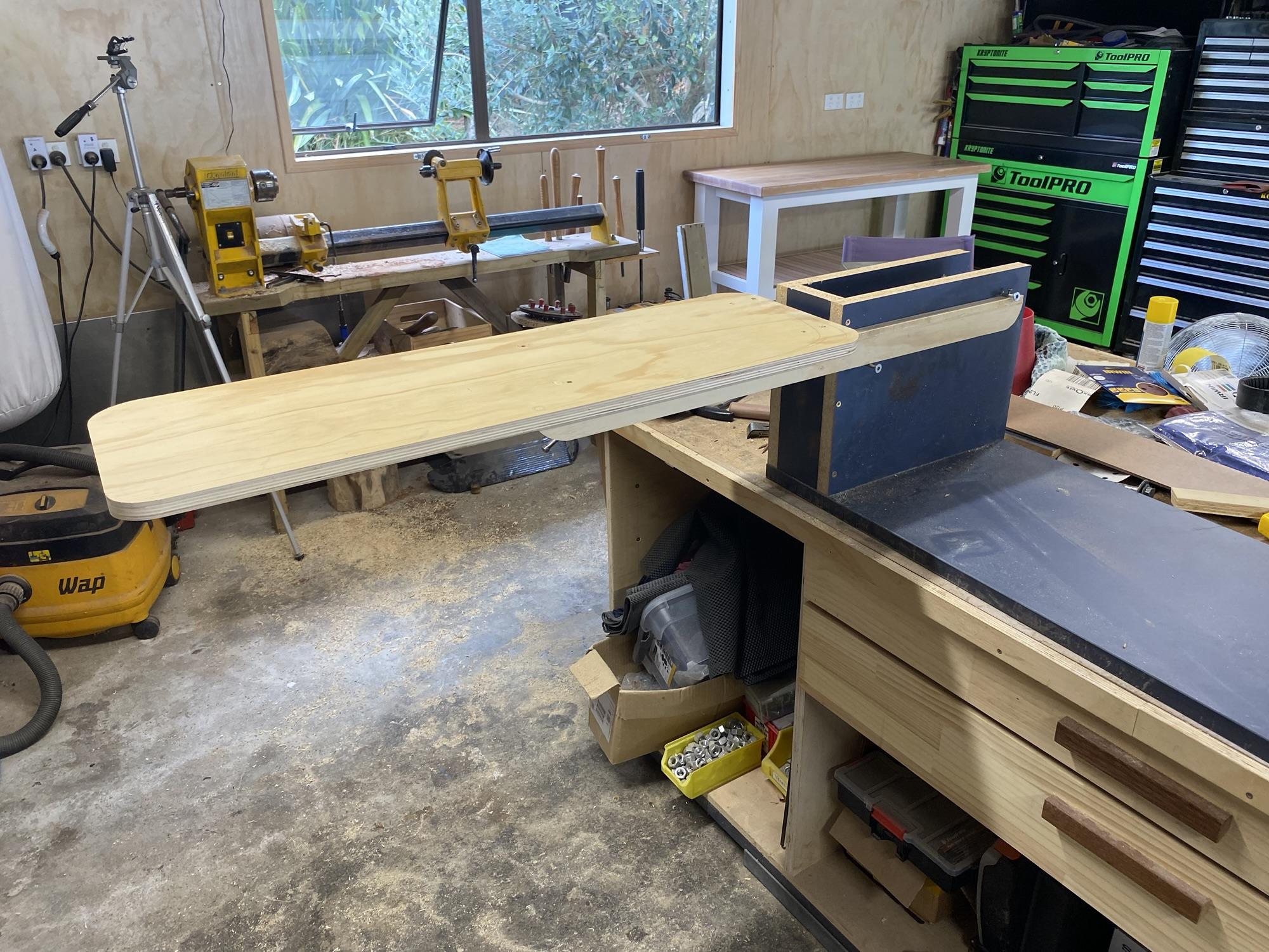
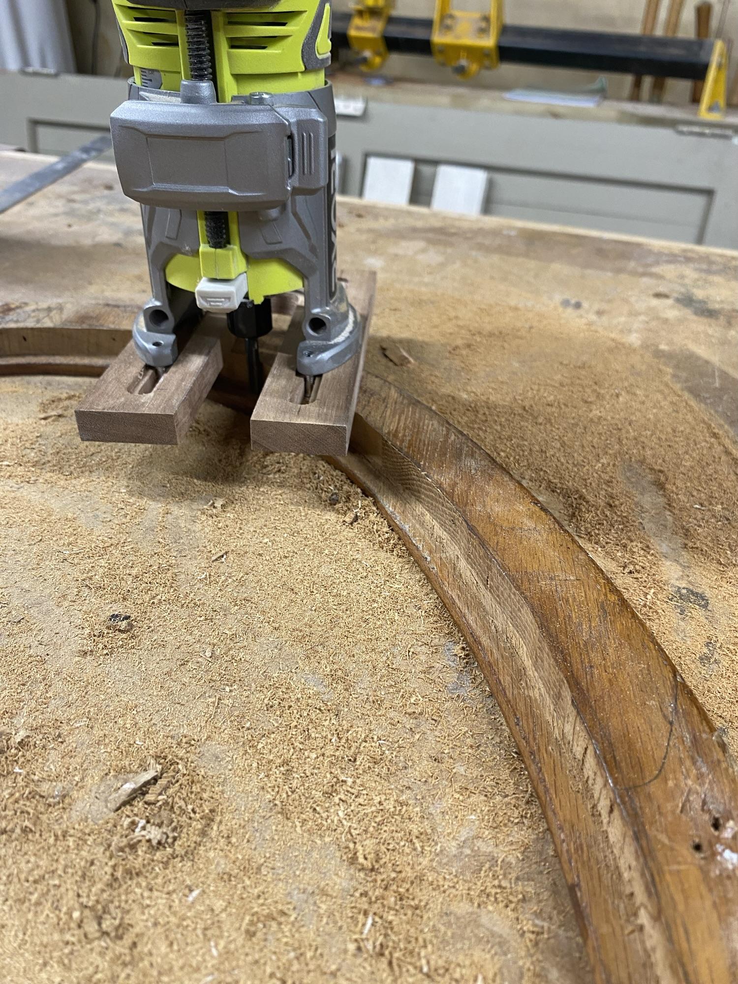
Instructions for use
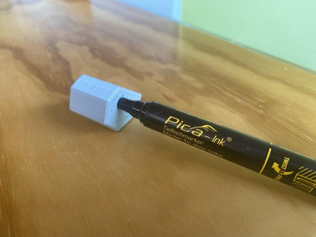
Be sure to use a 6.35mm bit for the first pass as that is what the jig is designed for.
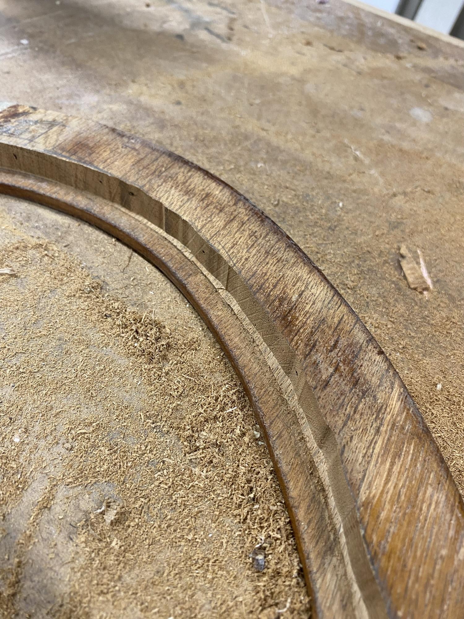
Decide on which edge to start and route your first groove using that edge as a guide, then slot the jig into the groove you just created and continue routing grooves. Once you’ve finished, swap your bit for your dovetail bit, and route the grooves in reverse order.
The reverse order is necessary to avoid the jig running through a slot that is too wide for the guide rail. By running through the slots in reverse, the last dovetail groove you cut should have the guide rail running up against the edge of the board the same as the first cut you made.